


The fundamental laws of Infrared heating
As IR heating has evolved, so has the fundamental science that underpins the workings of its heat transfer, but three main laws apply:
- Stefan-Boltzmann Law: Gives the total power radiated at a specific temperature from an IR source.
- Planck’s Law: Gives the spectral distribution of radiation from a black body source – one that emits 100% radiation at a specific temperature.
- Wien’s Law: Following on from Planck’s Law, this predicts the wavelength at which the spectral distribution of the radiation emitted by a black body is at a maximum point.
Steffan-Boltzmann Law
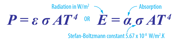
The Steffan-Boltzmann Law relates primarily to infrared emissivity. Calculating the power radiation from an IR source based upon the object’s surface area temperature and together with a black body factor. A perfect black body has a factor of 1 – with other materials varying in that factor (see table below). When we allow for the emissivity of normal materials the Stefan-Boltzmann Law becomes:
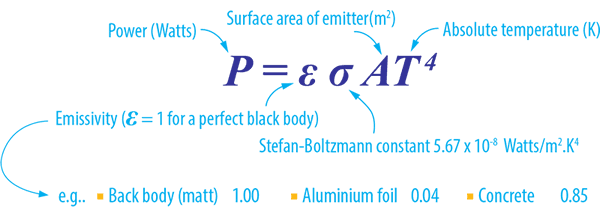
Within the definition of Kirchhoff’s law of thermal radiation, for any arbitrary body emitting and absorbing thermal radiation, the emissivity is equal to its absorptivity. This means that emissivity is useful to determine how much a surface will absorb as well as emit.
Table of emissivity of various surfaces
| Aluminium polished 0.09 | Brass polished 0.03 | Bronze polished 0.10 |
| Carbon ( candle soot ) 0.95 | Ceramic (glazed porcelain) 0.92 | Chromium polished 0.10 |
| Concrete 0.85 | Copper polished 0.02 | Copper oxidised 0.65 |
| Glass fused quartz 0.75 | Iron polished 0.21 | Iron rusted 0.65 |
| Plastic opaque 0.95 | Silver polished 0.05 | Stainless steel polished 0.16 |
| Stainless steel oxidised 0.83 | Water 0.96 |
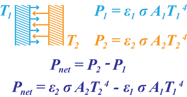
Using this law means we can now calculate the net heat transfer between two emitting surfaces at T1 and T2. As both are emitting, the net power transfer will be the difference between both emitted power outputs.
Planck’s Law
Planck’s Law describes the electromagnetic radiation emitted by a black body in thermal equilibrium at a definite temperature. It is named after Max Planck, a German physicist who proposed it in 1900.
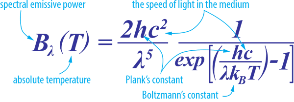
When plotted for various heater (emitter) temperatures, Planck’s law predicts:
- The range of frequencies across which infrared heating energy will be produced
- The emissive power for a given wavelength
Please see ‘Explanatory notes on Planck’s Law’ below.
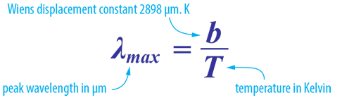
Wien’s Displacement Law
Wien’s Law is a follow on from Planck’s Law and predicts the wavelength at which the spectral distribution of the radiation emitted by a black body is at a maximum point.
A perfect black-body is a surface that reflects nothing and emits pure thermal radiation. The graph of power versus wavelength for a perfect black-body is called the black-body spectrum (see diagram below). Notice the dotted red line formed when we connect the maximum points of each temperature curve on Planck’s distribution and connect them.
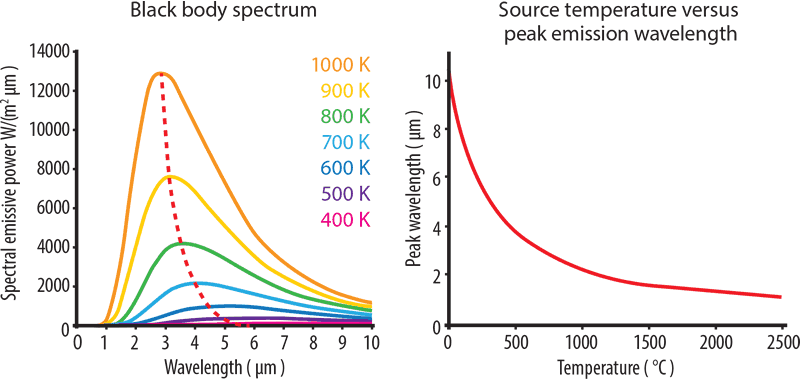
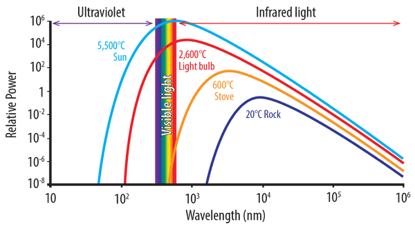
As the temperature rises, thermal radiation produces shorter wavelength, higher energy light. From the graph below, we can see how a light bulb produces a certain quantity of energy with only a small part in the visible spectrum. As temperature increases and the peak wavelength becomes shorter, the greater the amount of radiated energy.
The graph also shows that a rock at room temperature will not ‘glow’ as the curve for 20°C does not extend into the visible spectrum. As objects heat up, they start to give off visible light, or glow. At 600°C objects glow a dull red. At 1,000°C, the colour is yellow-orange, turning to white at 1,500°C.
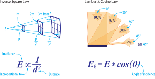
Two other scientific laws inform the practical application of infrared radiant heat – the Inverse Square Law and Lambert’s Cosine Law.
Inverse Square Law
The Inverse Square Law defines the relationship of radiant energy between an IR source and its object – that the intensity per unit area varies in inverse proportion to the square of that distance. However, in practice, the Inverse Square Law is less effective when concerned with large parallel surfaces, such as heated platens and oven systems.
Lambert’s Cosine Law
Lambert’s Cosine Law allows for the calculation of IR intensity when the radiation is not applied directly to the target body but is set at an angle. This law applies mainly to small sources radiating over a relatively large distance.
Infrared emitters used in industrial heating generally have a usable peak emission wavelength in the range of 0.75 to 10 μm. Within this range, there are three sub-divisions which are long, medium and short wave.
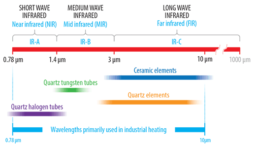
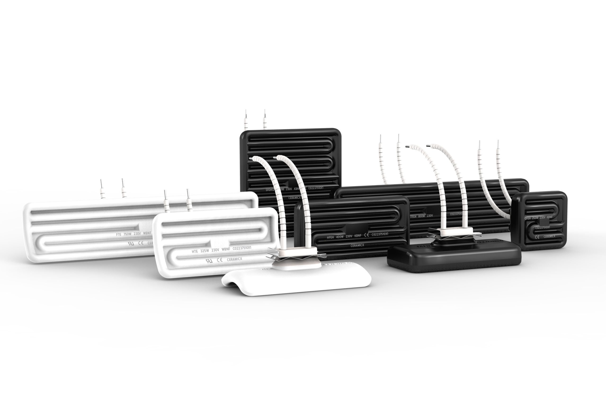
Longwave emitters, also known as far-infrared (FIR), have a peak emission range in the 3-10 μm range. This range generally refers to ceramic elements which consist of a high-temperature resistance alloy coil embedded into either a solid or hollow constructed highly emissive ceramic body. Ceramic emitters are manufactured in a number of industry-standard sizes with either flat or curved (trough style) emitting surfaces.
Shorter peak emission wavelengths are achieved by using emission sources with higher surface temperatures. Quartz cassette-style emitters are available in similar industry-standard sizes to that of ceramic and consist of a series of translucent quartz tubes built into a polished aluminised steel housing. These emitters can operate with higher front surface temperature and emit in the long to medium wave range.
At the shorter end of the medium wave range is the quartz tungsten emitter which consists of a sealed linear clear quartz tube containing a star design tungsten coil. The tungsten coil provides a fast response time with low thermal inertia.
The short wave quartz halogen range are of similar construction to that of the fast-medium wave tungsten emitter with the exception that a round tungsten coil is employed and quartz tubes are filled with halogen gas. The higher coil temperature results in the generation of white light and a peak emission wavelength in the short wave range.
Explanatory notes on Planck’s Law
Planck’s Law tells us that as the temperature of any emitting surface increases, more and more energy will be released as infrared energy. The higher the object temperature, the greater the amount of infrared energy will be produced. As well as becoming more intense (power) the emitted frequencies become wider and the peak wavelength becomes shorter.
At very high temperatures, not just infrared, some shorter wavelength visible light will also be produced. This is first witnessed as a dull red glow, then to orange, yellow, and finally white. Figure 1 (below) shows typical Planck’s Law curves for a range of temperatures plotted from 1050°C to 50°C.
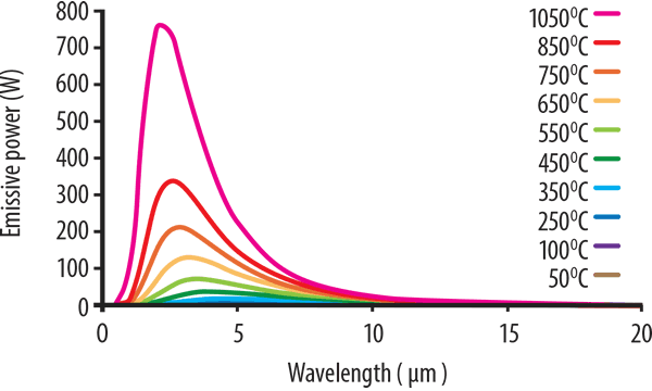
The pink curve corresponding to 1050°C exhibits the strongest output. It shows the highest power output and its peak is at around 2.5 microns. This is followed by the curve at 850°C where the peak energy is less than half of that produced at 1150°C.
As the temperature decreases, the energy levels also drop, and the peak energy wavelength shifts to the longer wavelengths. The lowest temperatures from the 250°C, 100°C, and 50°C curves cannot be seen in the graph, but when the graph is enlarged to see the lower temperature curves, this shift to the longer wavelengths is more apparent. However, the power intensity drops significantly.
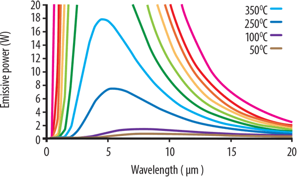
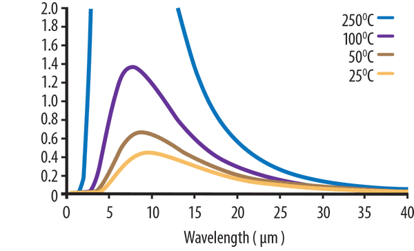
This is shown in Figure 2 (below). At 250°C, the blue curve can be seen to have an approximate peak ~ 6 microns, whereas at 100°C the peak wavelength is ~ 7.5 microns. Note also that the extent of wavelength is more evenly distributed and doesn’t exhibit the concentrated narrow peak seen at higher temperatures.
If we enlarge the same graph again and focus only on the lower temperatures as shown in Figure 3 (below), we see temperatures of 50°C and 25°C have peak wavelengths of ~ 9 and 10 microns respectively.
Applying this information
As experts in our field, we hope these pages of information will help you understand infrared better. The most important thing is to know what your material is and what you need your material to do. We can advise you on the rest!
Previous page: Application of infrared heat to materials