


| AUTHOR | DATE CREATED | VERSION | DOCUMENT NUMBER |
|---|---|---|---|
| Conor Newman | 18 July 2018 | V1.1 | CCII-00129 |
Introduction
A company is interested in heating the surface of a post-cure composite piece. The piece needs to be heated to approximately 230°C within 15 seconds.
Materials
The cured composite in this test is a carbon fibre reinforced epoxy resin with overall dimensions of 250mm x 130mm x 3.8mm.
Heaters
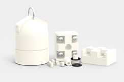
A variety of heaters were used for each test:
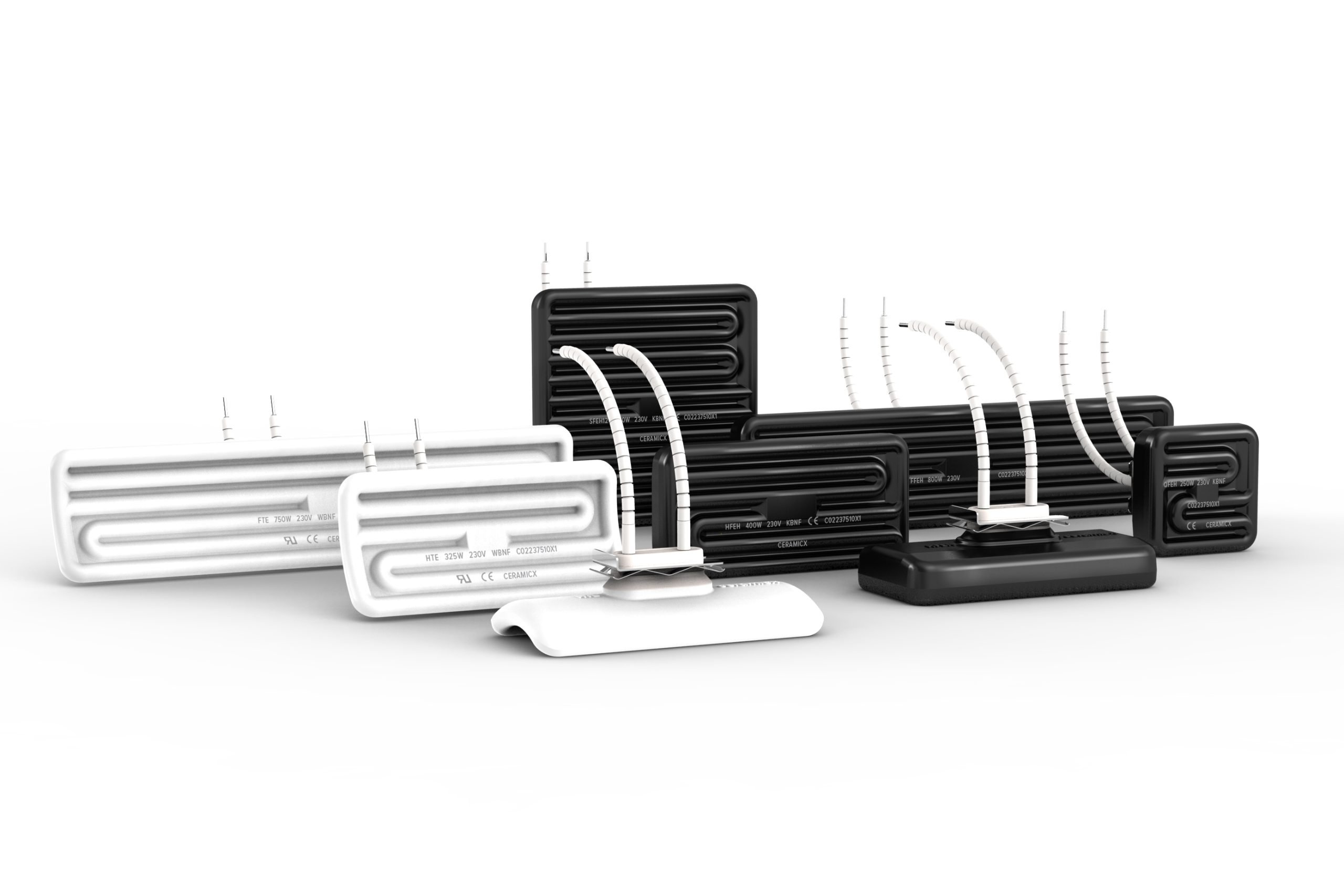
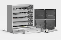
- 6 x 800W black FFEH (Ceramic full flat element hollow) Watt density = 44.8 kW/m2
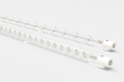
- 4 x 2kW QTL tubes (Quartz tungsten) Watt density = 56 kW/m2
- 4 x 1.5kW QHL tubes (Quartz halogen) Watt density = 42 kW/m2
Method
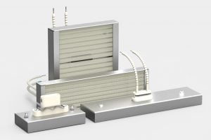
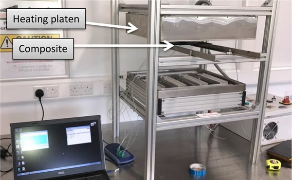
The composite material was placed under a specific array of varying heating elements. The top side of the composite was directly heated by the elements, and a number of type K thermocouples fixed on the top side of the composite to record the surface temperature. One t/c K was placed on the bottom surface for reference. The experimental set up can be seen in figure 1.
Results
All results obtained from the various tests are displayed both graphically and tabulated in this section.
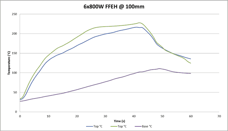
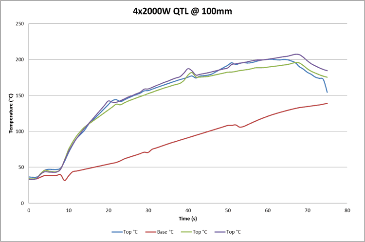
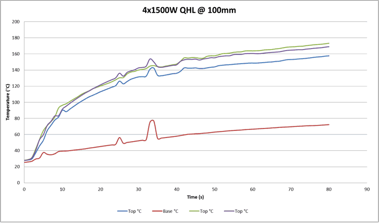
Figures 2, 3 and 4 display the results from heating the composite at a distance of 100mm.
With ceramic FFEH, the composite reached a max temperature of 227°C in 40 seconds.
- With QTL tubes, the composite reached a max temperature of 200°C in 65 seconds.
- With QHL tubes, the composite reached a max temperature of 170°C in 80 seconds.
After obtaining these results, it was clear that the long wave ceramic elements were by far best suited to heating the surface of this composite. However, the distance between the element and composite would have to be reduced in order to satisfy the required heating of 230°C in 15 seconds.
Figures 5 and 6 display the results from the reduced distance tests.
- At 60mm, the composite reached a max temperature of 280°C in 30 seconds. It reached 230°C in 16-18 seconds.
- At 50mm, the composite reached a max temperature of 350°C in 25 seconds. It reached 230°C in 12-14 seconds.
It must be noted that attemperatures greater than 250°C, the high temperature tape holding the thermocouples in place began to melt, potentially skewing results.
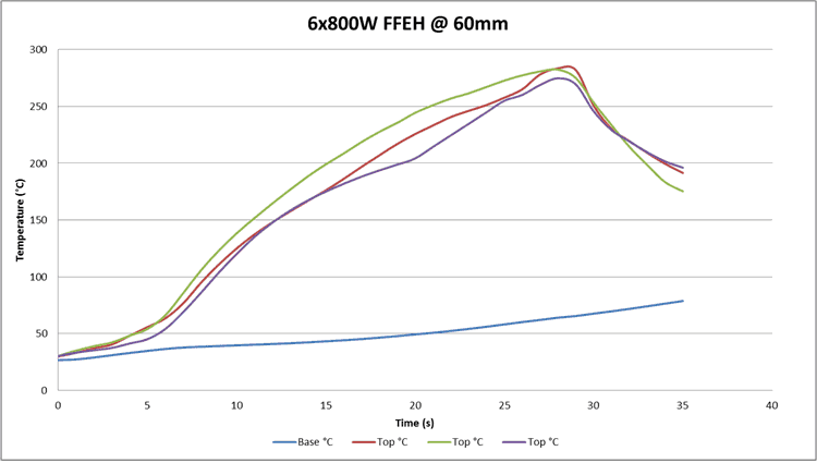
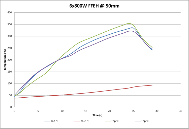
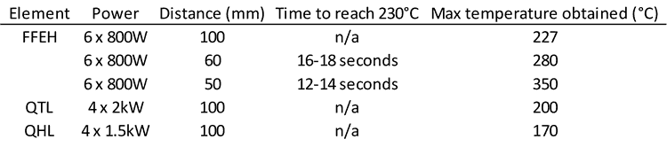
Table 1 tabulates the results from the entire test. It indicates that an array of 6 x 800W black FFEH elements, located 50mm above the composite, is sufficient to satisfy the requirements of the customers heating recipe.
Conclusion
- After testing each type of heating element (ceramic hollow, quarts tungsten, quartz halogen) at a fixed distance (100mm) it was found that the ceramic hollows were best suited to heating the surface of a composite.
- The QTL and QHL tubes provided better heating of the underside of the composite. This was expected, as these short wave elements are used in the curing of a composite in order to provide penetrative heating.
- The ceramic (long wave) elements expended the majority of thermal radiation to heat the top surface of the composite.
- 100mm was too large of a distance between the elements and the composite to reach the required temperature. 50mm was a suitable distance.
Disclaimer
These test results should be carefully considered prior to a determination on which type of infrared emitter to use in a process. Repeated tests conducted by other companies may not achieve the same findings. There is a possibility of error in achieving the set-up conditions and variables that may alter the results include the brand of emitter employed, the efficiency of the emitter, the power supplied, the distance from the tested material to the emitter utilised and the environment. The locations at where the temperatures are measured may also differ and therefore affect the results.