


| AUTHOR | DATE CREATED | VERSION | DOCUMENT NUMBER |
|---|---|---|---|
| Dr. Peter Marshall | 8 April 2016 | V1.1 | CC11 – 00101 |
Introduction
CCP Gransden approached Ceramicx to build an infrared oven to heat thermoplastic carbon fibre prepreg materials for their forming operations. This testing work was carried out as part of functions defined in the sales proposal (CSP 000 008). Phase one involves the infrared heater assessment and selection for this project, with the stipulated minimum material temperature being 425°C.
Material description
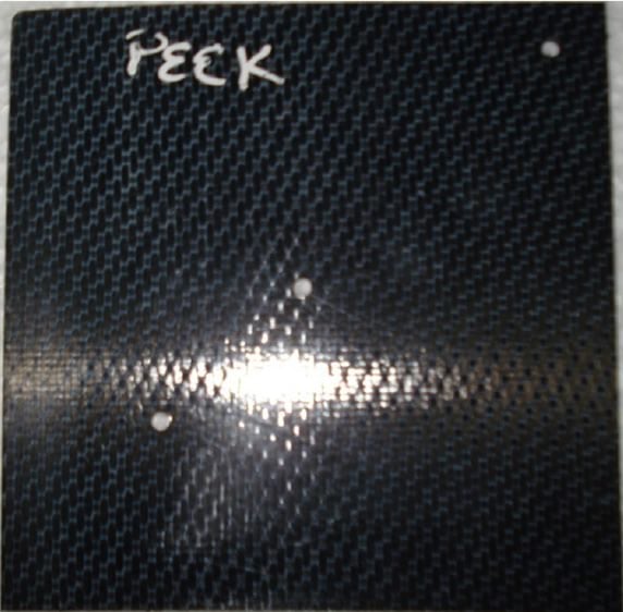
Three samples of two materials were received in 230 x 230 x 1mm pieces. In these cases, the matrix was PEEK1 and PPS2. A smaller sample of PEKK3 with dimensions of 200 x 150 x 2mm was also received. The material was rigid, smooth with a glossy black finish. A small pattern was visible on the surface on the surface of the PEEK and PPS samples.
The PEEK and PPS samples were cut into 115 x 115 mm pieces. The PEKK material was cut into 100 x 75mm pieces.
Method
Two distinct heater families were evaluated; halogen (QH and QT) and black hollow ceramic (FFEH). In each case, the platens were mounted above and below the material sample with adjustable height.
FastIR
A mounting system was manufactured to allow two of Ceramicx’s FastIR 500 units to be mounted above and below the material. A FastIR 500 consists of seven heating elements mounted in parallel fashion within a 500 x 500 mm case. The spacing between these tubes is 81mm. 1500W and 2000W ‘long’ (total length: 473mm) elements were used giving a total output from the two units of 21 or 28kW respectively. The heater units were mounted such that the distance between the element surface and the sample was varied between 55mm and 95mm.
The experimental protocol used was as follows:
- Fans switched on
- Central three heating elements switched on, top then bottom
- Outside four heating elements switched on, top then bottom
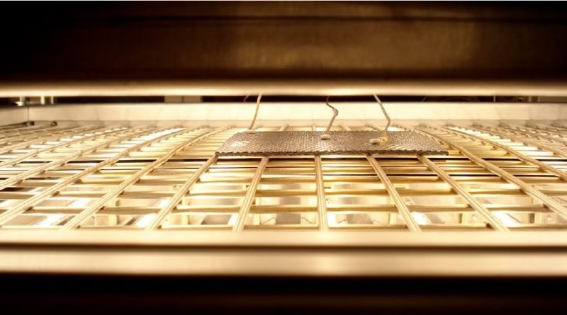
An image of a sample between the two FastIR units is shown in Figure 1. Nothing was used to enclose the gap between the two heating units
Elements
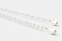
Two types of element can be mounted in the FastIR unit; quartz halogen and quartz tungsten. These elements emit different peak infrared wavelengths; halogen at approximately 1.0 – 1.2μm and tungsten between 1.6 – 1.9μm. Each tube has a diameter of 10mm, a total length of 473mm and a heated length of 415mm.
Black Hollow
A custom heating platen was designed to incorporate a 2 x 7 matrix of Ceramicx’s 800W FFEH elements, giving each platen 11.2kW of power. This matrix was enclosed in a 510 x 510mm case and mounted in the same frame as the FastIR system detailed above. The experimental protocol was used; however, fans were not employed in these platens. The distance between these elements was 65mm.
Two different element-sample distances were used, 50 and 100mm. Again, the gap between the two heating units was left open
Elements
Ceramicx black hollow elements emit peak wavelengths in the medium to long regime (2 – 10μm). Each element has dimensions of 245 x 60mm (l x w). The longer wavelengths associated with ceramic elements is very efficient for heating many polymeric materials.
Instrumentation
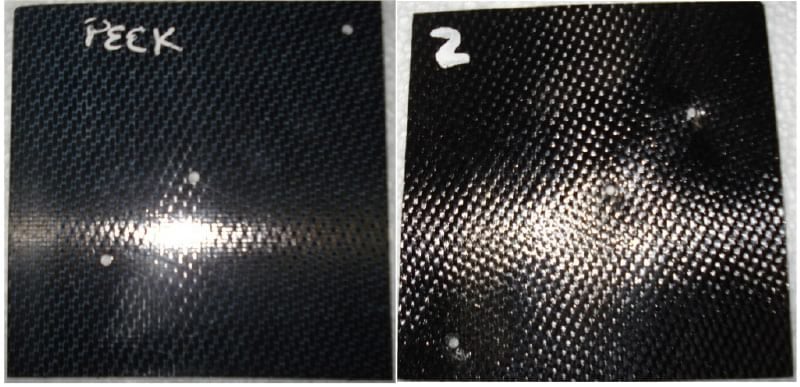
Type K thermocouples were affixed to the surface of the sample using M3 screws. Ceramic cement was trialled however this did not adhere to the surface of the material. Given the high temperatures required, no available adhesive would remain stable, so mechanical fixation was deemed necessary. The thermocouples were located at the centre of each specimen and also 10mm (edge) and 30mm (quarter) from the edge as shown in Figure 2. This located the thermocouples directly over the tube elements and in the centre between the elements so that the maximum temperature difference would be recorded. The temperature data was recorded at single second intervals.
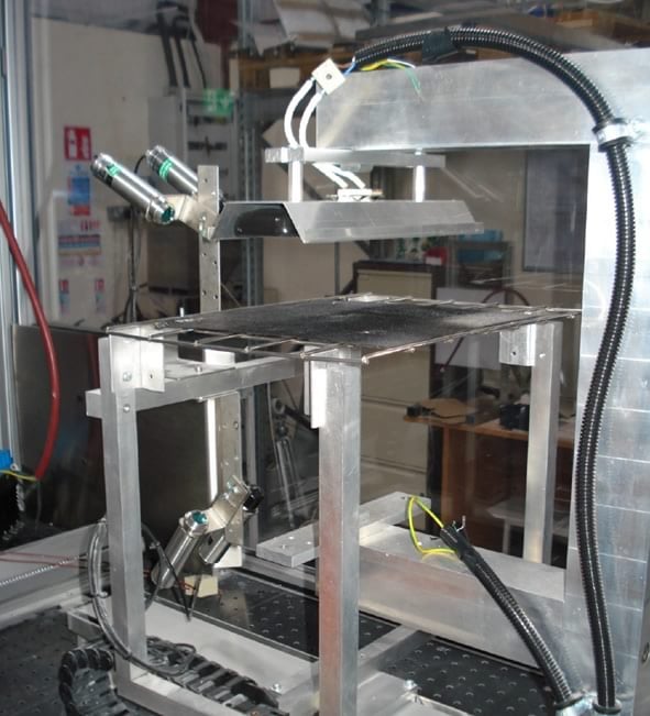
Sandwich testing
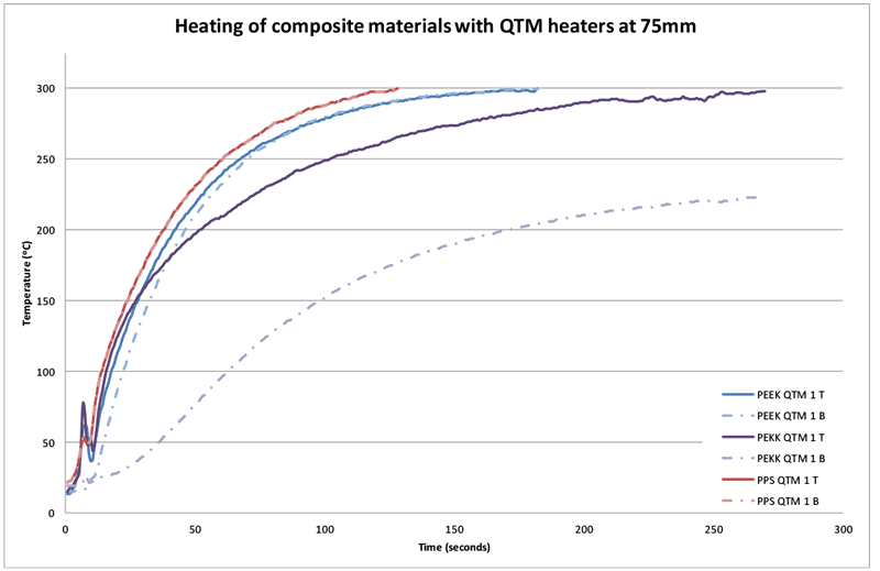
The sandwich tester is an advanced material thermal response testing machine as shown in Figure 2. Various types of infrared heaters can be mounted in two positions, facing vertically up and down. This ensures that the tested material can be heated from the top and/or the bottom. Four non-contact optical pyrometers are used to determine the top and bottom surface temperature of the tested material. The emitters are allowed to warm up to their operating temperature and the material is then brought under the emitter(s) for a predetermined period. This test was performed with both 1kW tungsten (QTM) and 800W black hollow elements (FFEH) mounted 75mm above the sample to determine which heater gave the best penetration through the material.
Results
FastIR
This section reports on the results found for tungsten and halogen tubes for the three materials in question. Tests were carried out with three different heater heights (55mm, 80mm & 95mm).
PEEK
Initial trials were conducted with a PEEK sample and the two FastIR heaters with 1500W quartz halogen tubes separated by 110mm. The results of this test, shown in Figure 4, indicate that the sample failed to reach the required temperature.
The elements were changed to 2000W shortwave halogen (QHL) tubes which showed that, at the same separation, the sample reached and exceeded the required temperature at one location. In this instance, the maximum temperature recorded was 485°C, however, significant temperature differences (up to 83°C) were also detected. The time required to reach the target temperature of 425°C was 99 seconds. This was achieved at two locations only
Quartz tungsten (QTL) tubes (2000W) were also examined at the three levels with maximum temperature falling off as heater distance increased. At 55mm, a maximum and minimum temperature of 520°C was detected. The target temperature, across the material sample was achieved in 206 seconds. Increasing the distance to 80mm, these reduced to 450°C and 415°C and at 95mm above the sample, the maximum and minimum temperatures of the sample were 407 and 393°C.
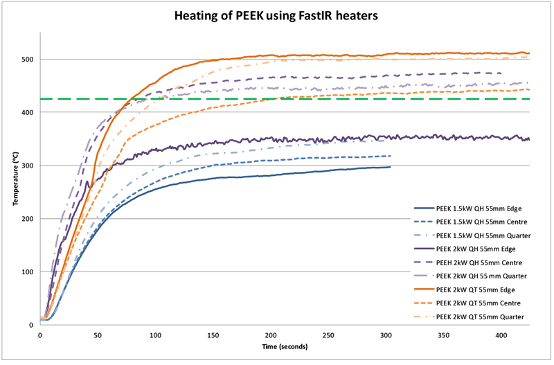
Figure 4 shows the variance in temperature that can occur across the sample due to the close proximity of the heaters to the sample as well as the time required to heat the material to 425°C (206 seconds for 2kW QT heater).
150°W tungsten tubes were not tested as it was deemed more operationally important to increase the heater distance than decrease the power of the elements used.
Figure 5 shows the visual difference in the sample before and after heating.
PEKK
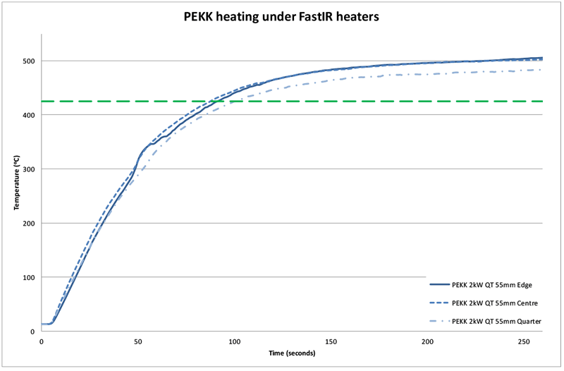
PEKK was heated with 2000W tungsten heaters at 55mm only. The thermal response of the material was excellent with temperatures in excess of 500°C being recorded. The minimum stipulated temperature was achieved in 102 seconds with the maximum temperature recorded being in excess of 500°C.
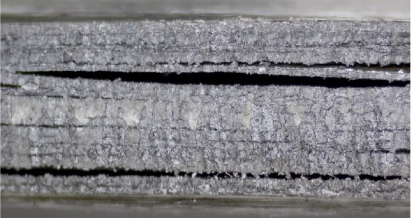
It was noticeable that this sample appeared to show some splitting and delamination at the edges and also some surface distortions following heating as shown in Figure 7, possibly from moisture absorption during storage and the rapid heating which occurred.
PPS
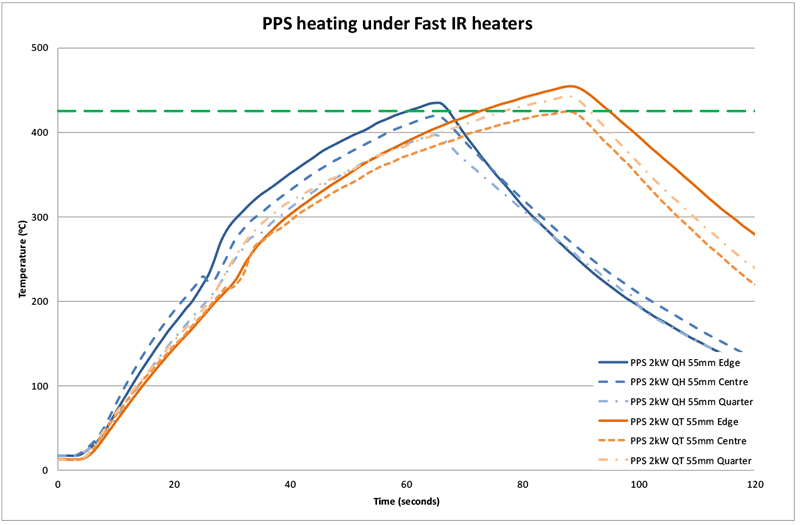
The PPS material was tested with 2000W halogen and tungsten heaters. The halogen test was carried out with a separation of 55mm and the tungsten tests at 55mm and 95mm.
The data again showed that the tungsten tube was a better heater for this material (than the halogen heater) with higher temperatures being recorded at the 55mm separation and also greater uniformity of temperature across the sample. A variation of 38°C was recorded for the halogen heaters and 30°C for tungsten heaters. This recorded variation will be highly influenced by the location of the thermocouple relative to the tubes. Identical thermocouple locations are not guaranteed.
Tests with PPS were terminated soon after the material reached the required temperature of 425°C as there was a release of sulphur smelling fumes from the samples.
At a distance of 55mm, the target temperature was recorded after 66 and 88 seconds for halogen and tungsten heaters at 55mm respectively. When the tungsten heaters were mounted at 95mm from the sample, the target temperature was not achieved.
Black Hollow
Initial tests were conducted with an element-material separation of 50mm. The temperature rise of the material was very rapid for all materials. From a cold start, hollow elements take approximately 10-12 minutes to heat to steady operational levels (surface temperature of approx. 700°C). The material temperature increase was broadly similar to the heating curve of the heater, however, there was a time lag in this.
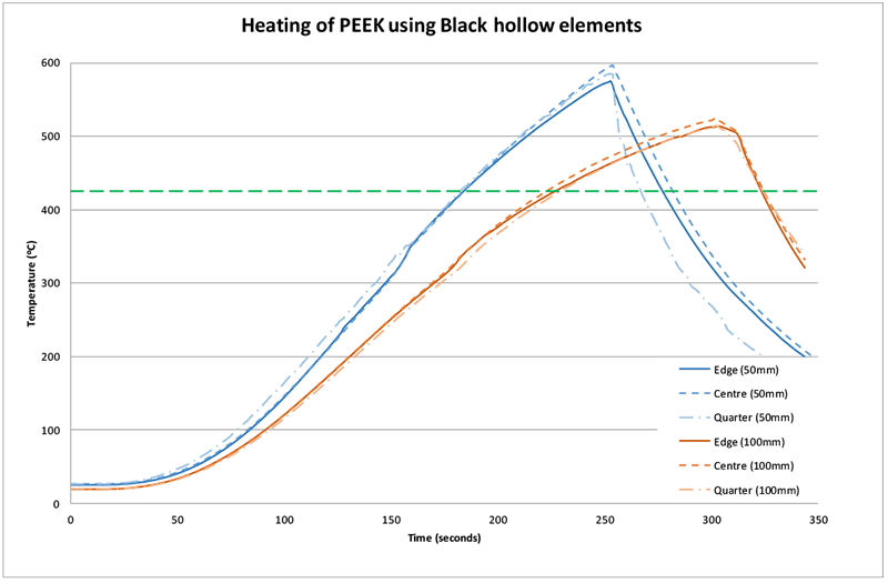
PEEK
A plot of the time taken to heat the sample of PEEK to reach the required processing temperature is shown below in Figure 9. This shows that the heating time to 425°C is approximately 185 seconds from when the heaters are turned on at 50mm. If the distance is increased to 100mm, the time is increased to 230 seconds. The sample was left between the two platens during heat up and removed for cooling.
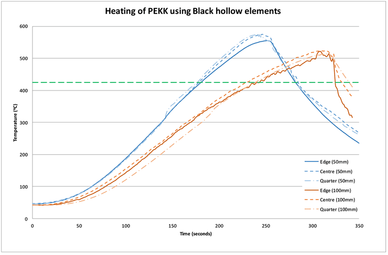
PEKK
The time taken for PEKK to reach the minimum threshold was slightly longer than for PEEK. Two possible reasons exist for this: 1.) the material does not absorb the infrared radiation as well as PEEK and 2.) the thickness of the material being twice as large (1 and 2mm respectively). The time required to reach 425°C at 50mm was 181 seconds and at 100mm this increased to 244 seconds
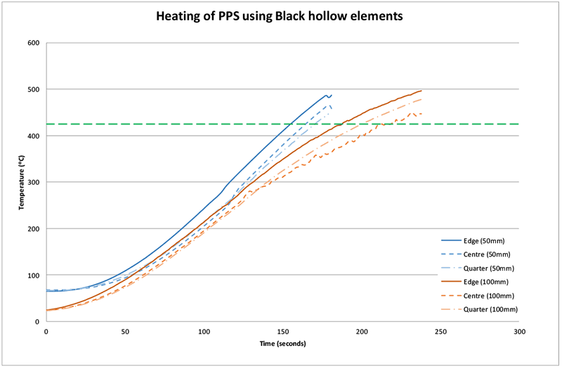
PPS
PPS heated very successfully with the black hollow elements with 425°C being recorded in 171 seconds and 219 seconds at 50 and 100mm respectively. The heating curve for this material is shown in Figure 11. Again, a release of sulphur smelling smoke occurred, however the quantity of this was not as much as with the halogen heaters as detailed above. This may partially be due to the absence of fans on the back of the heating platen.
A summary of the times required to heat the materials, with halogen, tungsten and hollow ceramic elements, to the target temperature is shown below in Table 1. As mounting the halogen elements at longer distances than 55mm was not universally successful, these results were omitted from the table.
|
Material |
Heater type (power)
|
Distance | Time to reach 425°C |
|---|---|---|---|
| PEEK | QHL (2kW) | 55mm | 99 |
| QTL (2kW) | 55mm | 206 | |
| FFEH (800W) | 50mm | 185 | |
| FFEH (800W) | 100mm | 230 | |
| PEKK | QTL (2kW) | 55mm | 102 |
| FFEH (800W) | 50mm | 181 | |
| FFEH (800W) | 100mm | 244 | |
| PPS | QHL (2kW) | 55mm | 66 |
| QTL (2kW) | 55mm | 88 | |
| FFEH (800W) | 50mm | 171 | |
| FFEH (800W) | 100mm | 219 |
Sandwich testing
Sandwich testing was carried out to obtain information about the transfer of heat through the material. This was done by heating the sample from a single side, measuring the temperature on both sides and comparing the results. Tungsten tubes and black hollow elements only were examined, as based on the FastIR results, the shortwave halogen tubes are not suitable heaters for the materials in question.
The results for QTM elements show that there is no significant temperature difference between the top and bottom surface for PEEK and PPS materials, however PPS heats more quickly and the curves for this material are virtually indistinguishable. It must be noted that these two materials are very thin (≈ 1mm). As expected, the temperature difference for PEKK was larger (75±2oC) due to its thickness (≈ 2mm). These results are shown in Figure 12 below.
For operational reasons, the test terminates when a temperature of 300°C is detected by the pyrometers. The peak seen in the first 30 seconds of the test is reflectance and is not a true temperature reading.
These results demonstrate that good IR penetration of the material is possible for PEEK and PPS using the tungsten type heater. However the temperature equalisation for PEKK is not as good, demonstrated by the almost 75°C difference in temperature in the last 18 seconds of the test4.
It was not possible to move the material samples closer to the heater to analyse what effect this would have as the acute angle required for the pyrometer to see the material would distort the reading.
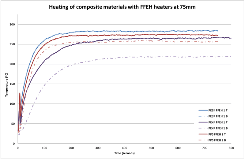
Heating of the samples with black hollow elements at the same distance (75mm) shows a similar trend with a larger temperature difference (45±2°C) being observed for the thicker PEKK material (compared with the thinner materials). The temperatures of the top and bottom surfaces of PEEK are virtually indistinguishable; however there is a difference in the temperature of PPS (25±2°C). This data is shown in Figure 13. This indicates that IR penetration of PPS with longer wavelength radiation is not as good as with shorter tungsten IR, however, the temperature equalisation of PEKK is better (but not ideal).
At 75mm separation, the highest temperatures and heating rates are obtained using the tungsten heater which appears to contradict the previous platen results. This however should not be used as a guide as only a single heater was used. Moreover, these characteristics will be improved by using an array of heaters as opposed to a single heater.
Conclusion
- The tests carried out and detailed above indicate that heating of the three thermoplastic carbon composite materials to a minimum of 425°C is possible with both medium-wave halogen and black hollow elements.
- Higher maximum temperatures are achievable using Ceramicx 800W black hollow element (FFEH).
- The time required to heat PEEK to 425°C was 206 seconds for 2kW tungsten tube heaters at 55mm and 230 seconds for FFEH elements at 100mm
- The time required to heat PEKK to 425°C was 102 seconds for 2kW tungsten tube heaters at 55mm and 244 seconds for FFEH elements at 100mm
- The time required to heat PPS to 425°C was 88 seconds for 2kW tungsten tube heaters at 55mm and 219 seconds for FFEH elements at 100mm
- The maximum temperatures, material heating rates achievable and surface temperature uniformity are a strong function of the distance at which the heaters are mounted from the material.
- Excellent IR penetration and therefore temperature equalisation, through the material thickness, of PPS and PEEK was achieved with medium-wave halogen (tungsten). The temperature equalisation achieved with PEKK was not as good as with the other materials.
- Excellent IR penetration and temperature equalisation was seen with PEEK using black hollow elements. This property was not as good as for PEKK and PPS.
Based on the test data above and the close element-material separations which are required to achieve the temperatures demanded to form the materials in question, it appears the best infrared emitter is Ceramicx 800W black full flat hollow element. While the times to achieve the required temperatures are slightly longer than the tungsten heaters, the closer proximity of the elements used will lead to better surface temperature uniformity. Furthermore, the ceramic elements were started from room temperature and required approximately 12 mins to reach operational levels. Therefore, this time could be significantly shorted by preheating the elements.
It should also be noted that these results are based on the samples which were made available for testing (i.e. 1mm and 2mm in thickness). Heating of thicker parts may require significant changes in heating technology to be investigated in order to ensure the temperature profile, across the material’s thickness, is uniform and suitable for subsequent forming operations.
1 Polyether ether ketone
2 Polyphenylene Sulfide
3 Polyetherketoneketone
4 Average difference between top and bottom surfaces taken over the last 18 seconds of the test.
Disclaimer
These test results should be carefully considered before a certain type of infrared emitter is determined to employ.
Repeat tests conducted by other companies may not achieve the same findings. Differences in the experimental conditions may alter the results. Other sources of error include: the brand of emitter employed, the efficiency of the emitter, the power supplied, the distance from the tested material to the emitter utilised and the environment. The locations at which the temperature is measured may be also cause variation in the results.